
Definitions
What is structured cabling (and what actually makes it supportable after handoff)?
Structured cabling is the planned, labelled, and tested cabling infrastructure that carries data, voice, and signals across a building. Here is what good structured cabling actually looks like in practice.
By Lume Technical Team · Published · Updated
Structured cabling is an organized system of cables, outlets, patch panels, and distribution points that connects equipment throughout a building. It is the physical foundation behind networked devices such as computers, phones, cameras, and wireless access points.
“Structured” describes how the connections are planned and managed. It is more than choosing a category of cable: the layout, installation, labelling, testing, and records all matter.
Follow one connection
At a desk, a short patch cord connects a computer to a data outlet. The fixed cable behind that outlet runs back to a patch panel in a telecommunications room. Another patch cord connects the panel to a network switch.
This arrangement lets the team manage connections at known points. When something changes, the records should identify the outlet, cable, panel port, and equipment involved.
What is usually included
- Horizontal cabling: runs from a telecommunications room to outlets or devices.
- Backbone cabling: links between rooms, floors, or buildings, often using fiber.
- Patch panels, racks, and cabinets: locations for organizing connections and equipment.
- Pathways: approved routes and supports for the cables.
- Labels and records: identifiers, drawings, port maps, and test results.
Cabling and network configuration are different tasks. A completed cable run still needs the appropriate equipment, power, and configuration for the connected device to work.
Choosing cable and planning distance
Category, intended speed, route length, environment, and device power requirements should be considered together. Avoid selecting cable solely because it is labelled “faster.”
A common commercial copper design allows a 90-metre permanent link and a 100-metre channel including cords, with design conditions that can reduce the available length. Fluke Networks explains permanent links and channels. Fiber or a different distribution layout may be appropriate where a route does not fit the design limits.
What makes the installation supportable
- Identifiers match. Outlet and panel labels correspond to the drawings and result files.
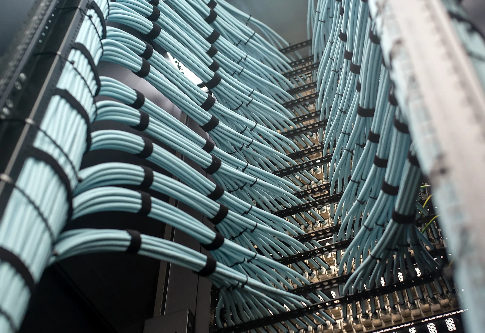
- The route is manageable. Cable supports, bend radii, separation, and rack access have been considered.
- Tests match the specification. The agreed test configuration and category limits are used, with results linked to cable identifiers.
- Drawings reflect the finished site. Changes during construction appear in the final records.
- The records have an owner. The team knows where the documentation is stored and how later changes will be recorded.
“Closeout” means the final handoff of these records and any remaining issues. It should be part of the agreed scope.
Connected does not necessarily mean certified
A basic check can show whether conductors are connected. Certification evaluates a cabling link against defined performance limits. Specify which checks are required and which files you expect to receive.
For fiber links, agree insertion-loss testing and any additional OTDR characterization appropriate to the scope. Do not treat every cable type as requiring the same test.
Questions worth asking before work starts
- What cable, pathway, and termination choices are included?
- Which areas, outlets, and devices are covered?
- What test configuration and acceptance limits will be used?
- How will access and outages be coordinated?
- Which drawings, photos, and test records will be handed over?
- Who will resolve exceptions or outstanding items?
Explore Lume’s structured cabling service or discuss an upcoming project.